Initial comments
As part of the move from the ADCD provided systems to the standard image, I found that existing device map with not migrated to the new system. This challenge gave me the opportunity to learn about configuring the I/O subsystem and Hardware Configuration Definition (HCD) for ZD&T, zPDT and the standard image.
HCD documentation is available online or as PDFs.
Concepts
The I/O configuration is pointed to by the LOAD member in SYS1.IPLPARM or SYS0.IPLPARM
For example
*---+----1----+----2----+----3----+-
IODF 05 PROV DEFAULT 00
...
Where the columns are important. This would use dataset PROV.IODF05 and look for system DEFAULT.
The names of the production IODFs are id.IODFnn where nn is 00 to 99
You can display the currently active HCD by using operator command
Activate test
To configure the HCD you use ISPF. On my system to get to the HCD application you need option 12;2
- 12 z/OS System z/OS system programmer applications
- 2 HCD HCD I/O configuration
When working with HCD you cannot update the currently active, you use a working dataset, and create a new IODF image at the end.
With input fields ending in a +, you can use PF4 to display the available options.
Basic configuration
You define a device range, for example 0700 for 16 units; and the device type 3277.
For these to be visible in z/OS the devices must be connected to an operating system definition. I spent many an hour trying to work out why my newly configured DASD was not in my z/OS system – it was because I had not connected the devices.
Print the configuration
Once you have made changes, you should print the configuration and check they are as you expect, for example the devices are connected to the operating system.
//IBMHCD JOB MSGCLASS=H //GCREP EXEC PGM=CBDMGHCP, // PARM='REPORT,CSMEN,,,,,00' //HCDIODFS DD DISP=SHR,DSN=PROV.IODF06 //* DIODFS DD DSN=PROV.IODF05,DISP=SHR //HCDRPT DD SYSOUT=H, // DCB=(RECFM=FBA,LRECL=200,BLKSIZE=6400) //HCDMLOG DD SYSOUT=H, // DCB=(RECFM=FBA,LRECL=200,BLKSIZE=6400)
The output is like
                                        DEVICE SUMMARY REPORT
 --- DEVICE ---    DEVICE
  NUMBER,RANGE    TYPE-MODEL             ATTACHING CONTROL UNITS
 ______________  _____________  |____|____|____|____|____|____|____|____|
    0700,64      3277-2
    0A80,64      3390
    0AA0,64      3390
...
                                       OPERATING SYSTEM SUMMARY REPORT
   OPERATING                                                          D/R
   SYSTEM ID   TYPE        GEN    DESCRIPTION                         OS I
   _________   ________    ___    ________________________________    ____
   DEFAULT     MVS                Default OS Config
                                        MVS DEVICE REPORT
   OPERATING SYSTEM CONFIGURATION ID:  DEFAULT
DEV#,RANGE  TYPE-MODEL   SS  BASE  UCB-TYPE  ...
__________ _____________ __  ____  ________  ...
0700,64    3277-2         0        12001009  ...
0AA0,64    3390           0        3030200F  ...
and note device range 0A80 for 64 is not in the DEFAULT system configuration. At IPL this range of devices will not be there.
What is my current configuration?
The operator command ACTIVATE TEST gives
activate test ... IEF196I IEF285I PROV.IODF05 KEPT IEF196I IEF285I VOL SER NOS= OPEVS1. IEF196I IEF285I PROV.IODF05 KEPT IEF196I IEF285I VOL SER NOS= OPEVS1.
Configuring the HCD
ISPF 12;2 gave me
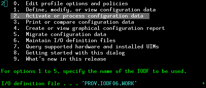
                           Hardware Configuration

Select one of the following.

1   0.  Edit profile options and policies
    1.  Define, modify, or view configuration data
    2.  Activate or process configuration data
    3.  Print or compare configuration data
    4.  Create or view graphical configuration report
    5.  Migrate configuration data
    6.  Maintain I/O definition files
    7.  Query supported hardware and installed UIMs
    8.  Getting started with this dialog
    9.  What's new in this release

For options 1 to 5, specify the name of the IODF to be used.

I/O definition file . . . 'PROV.IODF04'____ + - At the bottom, I/O Definition file – put the cursor in the input field and press PF4, to display the available files.
- Select 1 Define, modify, or view configuration data.
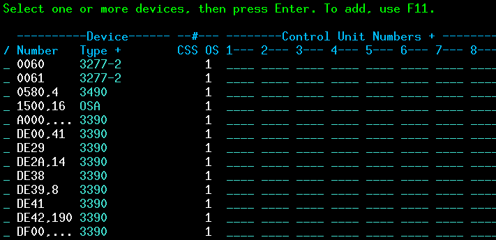
This gives lines with
- The start address, and count. For example DE00, for 41 ( so address range DE00 to DE40)
- The device type: 3390
- OS 1… connected to the 1st system definition. If this is blank it is not connected,
- Press PF11 to add a device (or put D in the line command for an entry to delete an entry). This may display
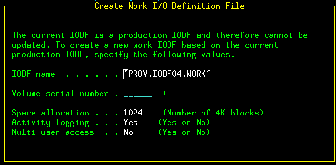
This is creating a work file, so you do not update the currently active one. Specify the volser
You will get
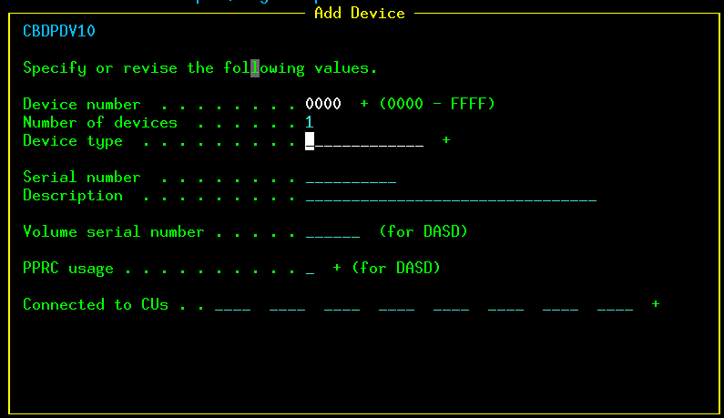
Specify an address, and a count of addresses. Put the cursor in the Device type input file and press PF4 ( as indicated by the + sign at the end of the field).
This gives

This is the list of systems you can connect the I/O devices to. Put a / in front of the config id (DEFAULT) and press enter. This gives

Select 1 because you want to connect the device to the DEFAULT system.
This gives
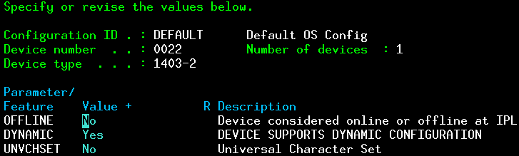
You can customise the options. Each device type has different options. Press enter till you get back to the I/O Device List (with your address range added).
Generate the production IOCD
From the initial panel select option 2. Activate or process configuration data, and specify the work dataset.
The I/O definition dataset name at the bottom should be the one you are currently working with. You can use PF4 to display the datasets names you have worked with.

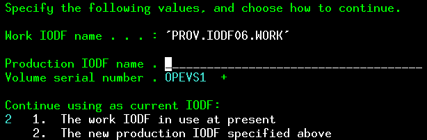
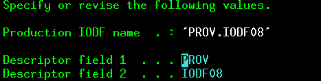
Enter a new data set name, such as PROD.IODF08, and the volume serial. (I think this is the same volume as your SYSn.IPLPARM dataset.
Press enter for
Print the IODF using the JCL above.
Update your LOADXX member with the new number, and when you next IPL the changes should be active. ( I created a new LOADYY member, so I could go back to the old IODF if I had problems.)
Export a definition
You can use the ISPF dialogs to exportthe definitions. It prompts for node and userid. If you specify * for both, it will XMIT the definitions to a dataset userid.EXPORTED….
You can import an exported definition through the ISPF dialogs.
What systems and consoles are defined?
You can define consoles in the IOCD – you still need to have the z/OS CONSOLE definition.
From the HCD main panel, select
- 1. Define, modify, or view configuration data
- 1. Operating system configurations

if you select the default configiguration with / and press enter it gives
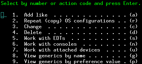
You can either select by number, or note the letter at the end of the line. Work with console -> n.
You can specify this command (‘n’) in
to go directly to the console definitions.
This gives
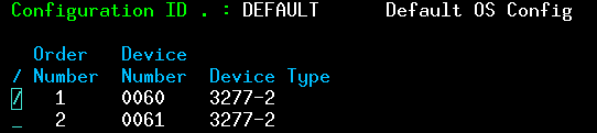
so you can see there are two console defined. One at address 0060, the other at address 0061.
The old zD&T IODF
The IODF from the ZD&T IODF is below. Ive simplified it – replacing 0700,1; 0701,1; 0702,1 etc with 0700,64.
----------Device------ --#--- --------Control Unit Numbers + -------- / Number Type + CSS OS 1--- _ 000C 2540 ____ _ 000C 2540R-1 1 ____ _ 000E,2 1403-N1 1 ____ _ 0120 3380 64 ____ _ 01C0,64 3390 ____ _ 0240,32 3380 ____ _ 0260,32 3390 ____ _ 0300,25 3390 1 0300 _ 0400,16 OSA 1 ____ _ 0550,16 3420-8 1 ____ _ 0560,16 3480 1 ____ _ 0580,16 3490 1 0580 _ 0590,16 3590 1 0590 _ 0600,16 3390 1 ____ _ 0900 3270-X 32 ____ _ 0A80 3390 64 ____ _ 0E20 CTC 4 ____ _ 0E40 CTC 4 0E40 _ 1A00,256 3390 1 ____ _ 2A00,256 3390 1 ____ _ 3A00,256 3390 1 ____
