One minute networking: IPV6 Multi cast for people who do not want to know the details.

I picture IP multicast as groups in whatsapp, or to send a packet of data to all endpoints under a node in the network.

The maximum group is the top 104 bits of an IP V6 TCPIP address – or, to put it a different way, having a different right 24 bits.

With an IP address of 2001:0123:4567:89ab:cdef:0123:4567:89ab the maximum group is 2001:0123:4567:89ab:cdef:0123:45..:…. to send a packet to members of the group you use address ff02:0000:0000:0000:0000:0001:ff.:…. or (in abbreviated form) ff02::1:ff .

There are different groups. One of my interfaces is a member of the following “groups”

  • ff01::1 all nodes
  • ff02::2 all routers
  • ff02::1:ff67:89ab this is a group for this specific address. When an interface is started, it sends a packet saying “does anyone have this address 67:89ab” to the group ff02::1:ff67:89ab. If there is a reply – then the value you are using is a duplicate. This is known as DAD Duplicate Address Detection.
  • ff02::fb multicast DNS IPv6

IP V4

When an IP V4 interface starts it broadcasts (similar to multicast) “ARP: I am address 10.1.1.2, this is my MAC address, and I my status is UP”

Displaying multicast information on Linux

linux netstat –groups

This gives information like

IPv6/IPv4 Group Memberships
Interface RefCnt Group
--------------- ------ ---------------------
lo 1 mdns.mcast.net
lo 1 all-systems.mcast.net
eno1 1 mdns.mcast.net
eno1 1 all-systems.mcast.net
...
lo 1 ff02::fb
lo 1 ip6-allnodes
lo 1 ff01::1
eno1 1 ff02::fb
eno1 1 ff02::1:ffa8:b879
eno1 1 ip6-allnodes
eno1 1 ff01::1
...

Where ip6-allnodes is ff02::1

For z/OS

For an interface with addresses 2001:db8:8::f and 2001:DB8::0067:89ab
TSO NETSTAT DEVLINKS

IntfName: JFPORTCP6         IntfType: IPAQENET6  IntfStatus: Ready 
...
Multicast Specific:
Multicast Capability: Yes
Group: ff02::1:ff67:89ab
RefCnt: 0000000001 SrcFltMd: Exclude
SrcAddr: None
Group: ff02::1:ff00:4
RefCnt: 0000000001 SrcFltMd: Exclude
SrcAddr: None
Group: ff02::1:ff00:9
RefCnt: 0000000001 SrcFltMd: Exclude
SrcAddr: None
Group: ff02::1:ffa2:a2a2
RefCnt: 0000000001 SrcFltMd: Exclude
SrcAddr: None
Group: ff01::1
RefCnt: 0000000001 SrcFltMd: Exclude
SrcAddr: None
Group: ff02::1
RefCnt: 0000000001 SrcFltMd: Exclude
SrcAddr: None
  • ff02::1:ff67:89ab is a group for the address 2001:DB8::0067:89ab
  • ff02::1:ff00:9 is group for the address with 2001:db8:8::9
  • ff01::1 is for all nodes.

Issuing the first ping

I have a laptop connected to a server over Ethernet. The laptop had address 2001:7::1, and the server had IP address 2001:7::2. I defined a route from the laptop to the server

The first time an IP address 2001:7::2 was used on the laptop, there was a flow to all nodes ff02::1:ff, for address 2001:7::2, and a response from 2001:7::2

2001:7::1 ff02::1:ff00:2 ICMPv6 Neighbor Solicitation for 2001:7::2 from ...
2001:7::2 2001:7::1 ICMPv6 Neighbor Advertisement 2001:7::2 (sol, ovr) is at ...

This sends a request from 2001:7::1 to all routers asking “does any one have address 2001:7::2”. Device 2001:7::2 advertises to 2001:7::1 “I have the address”.

One minute networking: getting your data to flow around the corner; IP tunnelling

This is another of the little bits of networking knowledge, which, once you understand it, is obvious! Some of the documentation on the web is either wrong or is missing information.

The original problem

I wanted to use a route management protocol (OSPF) for managing the routing information known by each router. It has its own format packets. Not every device or router supports these packets.

You configure the interface name, and the OSPF data flows through the interface.

When the connection is a direct line, the data is passed to the remote system and it can use it. When the connection is indirect, for example via a wireless router. The wireless router does not know how to handle the OSPF packets and throws them away. The result is that my remote machine does not get the OSPF packets.

The solution – use a tunnel

One solution is to wrap the packets of data, so they get passed up to the router, round the corner, and back down to the remote system.

When I was employed, we had an internal mail system for paper correspondence . If we wanted to send a letter to a different site, we took the piece of internal mail, put it in an envelope and sent it through the national mail to the remote site. At the remote site, the mail room removed the external envelope, and sent the internal letter on to the recipient. It is a similar process with IP tunnelling.

I have a laptop with IP address A.B.C.D and a server with address W.X.Y.Z., I can ping from A.B.C.D to W.X.Y.Z, so there is an existing path between the machines.

You define a tunnel to W.X.Y.Z (the external envelope) and give which interface address on your system it should use. (Think of having two mail boxes for your letter, one for Royal Mail, another for FedEx).

You define a route so as to say to get to address p.q.r.s use tunnel ….

The definitions

The wireless interface for my laptop was 192.168.1.222 . The wireless address of my server was 192.168.1.230

I defined a tunnel from Laptop to Server called LS

sudo ip tunnel add LS mode gre local 192.168.1.222 remote 192.168.1.230 

Make it active and define the address on the server 192.168.3.3 .

sudo ip link set LS  up
sudo ip route add 192.168.3.3 dev LS

If I ping 192.168.3.3 the enveloped packet goes to the server machine 192.168.1.230 . If this address is defined on the server the ping sends a response – and the ping worked!

Except it didn’t quite. The packet got there, but the response did not get back to my laptop.

At the server the ping “from” IP address was 10.1.0.2, attached to my laptop’s Ethernet. This was not known on the server.

I had three choices

  • Define a tunnel back from the server to the laptop.
  • Use ping -I 192.168.1.222 192.168.3.3 which says send the ping request to 192.168.1.1 , and set the originator address to 192.168.1.222. The server knows how to route to this address.
  • Define a route from the server back to my laptop.

The simplest option was to use ping -I … because no additional definitions are required.

This does not solve my problem

To get OSPF data from the server to my laptop, I need a tunnel from the server to my laptop; so a tunnel each way

Different sorts of data are used in an IP network

  • IPV6 and IPV4 – different network addressing schemes
  • unicast and multi cast.
    • Unicast – Have one destination address, for example ping, or ftp
    • Multicast – Often used by routers and switches. A router can send a multicast broadcast to all nodes on the local network for example ‘does any nodes have IP address a.b.c.d?‘. The data is cast to multiple nodes.

When I defined the tunnel above I initially specified mode ipip. There are different types of tunnel mode ipip is just one. The list includes

  • ipip – Virtual tunnel interface IPv4 over IPv4 can send unicast traffic, not multi cast
  • sit – Virtual tunnel interface IPv6 over IPv4.
  • ip6tnl – Virtual tunnel interface IPv4 or IPv6 over IPv6.
  • gre – Virtual tunnel interface GRE over IPv4. This supports IPv6 and IPv4, unicast and multicast.
  • ip6gre – Virtual tunnel interface GRE over IPv6. This supports IPv6 and IPv4, unicast and multicast.

The mode ipip did not work for the OSPF data.

I guess that the best protocol is gre.

Setting up a gre tunnel

You may need to load the gre functionality

sudo modprobe ip_gred
lsmod | grep gre

create your tunnel

sudo ip tunnel add GRE mode grep local 192.168.1.222 remote 192.168.1.230 
sudo ip link set GRE up
sudo ip route add 192.168.3.3 dev GRE

and you will a matching definition with the same mode at the remote end.

Displaying the tunnel

The command

ip link show dev AB 

gives information like

9: AB@NONE: mtu 1476 qdisc noqueue state UNKNOWN mode DEFAULT group default qlen 1000 link/gre 192.168.1.222 peer 192.168.1.230

where

  • link/gre this was defined using mode gre
  • 192.168.1.222 the local interface to be used to send the traffic
  • peer 192.168.1.230 the IP address for the far end

The command

ip route 

gave me

192.168.3.3 dev AB scope link

so we can see it gets routed over link(tunnel AB).

Using the tunnel

I could use the tunnel name in my defintions, for example for OSPF

interface AB
area 0.0.0.0

One minute networking: TCP buffer sizes

When data flows over a TCPIP connection there are several factors which control the rate at which data can be sent. You can influence some of these factors.

Data is sent as packets typically of size about 1440 bytes – because old hardware could only support this. You could use larger packets, but you may hit a router which chops it into smaller blocks.

The basic TCPIP flow

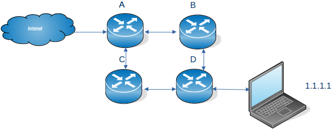
Consider a Client Server connection. The client application wants to send some data to a server application

  • The client uses send() to put some data into a TCPIP buffer and returns.
  • TCPIP sends some data (a packet) from this buffer, sets a timer and waits.
  • The server receives the data, end sends back an ACK saying so far I have received this many bytes from you.
  • The application on the server does a receive (if there is no data, the application is suspended until data arrives). If there is enough data to satisfy the receive, the application returns, otherwise it is suspended.
  • At the client end, when TCPIP has received the ACK. It no longer needs the data which has just been acknowledged. It can send more data.
  • If no ACK was received and the timer has timed out, TCPIP resend the data.

There are several parts to this:

  • Putting things into the pipe – the send buffer
  • The pipe
  • Getting things from the pipe, the receive buffer

The send buffer

  • TCPIP has a buffer for its use.
  • The application
    • An application does a send() and passes data to TCPIP.
    • If there is space in the TCPIP buffer, the data is moved into the buffer, and the application returns.
    • If there is not enough space for all of the data, enough data is moved to fill the buffer, and the application waits until more space is available in the buffer.
    • When all of the data has been passed to the TCPIP buffer, the application returns, and can do more application work.
  • TCPIP
    • TCPIP takes a chunk of the buffer (a packet) , sends it over the network, and sets a timer.
    • It can then process another chunk of data, and send it over the network, so there are multiple packets in flight.
    • When the far end has passed the data to the application, it sends the ACK back.
    • The local end, when it has received the ACK for a chunk of data, knows the data has been received by TCPIP at the remote end, it no longer needs to keep a copy of the data, and frees up the space on the buffer.

How big a buffer is needed to get good throughput?

The data is held in the TCPIP buffers; waiting to be sent plus the round trip time; from when the data was put into the TCPIP buffer, to getting the ACK back. This could be 10s of milliseconds. Multiple packets can be in-flight (perhaps 10s or 100s) which improves the throughput. So send 10 packets; wait, when the first ACK is received, send another packet etc., so there are always 10 packets in flight.

If the buffer is too small the application has to wait. Increasing the send buffer size will increase throughput up to a point (when the application does not have to wait) after this point making it larger may make no difference.

As more data is in flight, the connection needs a bigger send buffer.

An application can set the send buffer size using the SETSOCKOPT call. If this is not used, then there will be a TCPIP default send buffer size. On z/OS this is the system wide TCPCONFIG TCPSENDBFRSIZE …. parameter.

The default used to default to 16KB, and currently is typically 64KB. There is a TCPIP enhancement which says if the send buffer size is larger than 64KB, then TCPIP can dynamically increase it if it will improve performance. See Outbound Right Sizing(ORS).

Note: If you change the system wide send buffer size (TCPCONFIG TCPSENDBFRSIZE on z/OS), this will affect all applications that do not set the size using SETSOCKOPT. You should test this before putting it into production because it may affect many applications.

The receive buffer

At the receiving end, TCPIP has a buffer. Data from the network is put into this buffer. After the data has been put into the buffer, TCPIP sends back an ACK with three fields saying

  • so far I’ve received this many bytes from you
  • I’ve sent you this many bytes
  • my buffer has space for this many bytes

An application does a receive to get the data, if there is insufficient data to satisfy the receive, the application can wait, or return just the data in the buffers, depending on the options.

If the receive buffer is full, any incoming data will be thrown away. If the application does receive the data, then does lots of processing on the data, followed by receive more data etc, the receive buffer may fill up. Some applications receive the data, give the data to a subtask to process, immediately do another receive, and so try to keep the receive buffer empty.

If the amount of arriving data is larger than the free space in the buffer, TCPIP will return “no space left in the buffer” as part of an ACK. The sender then knows to wait. When the application receives the data, and makes space, “x bytes are available in the buffer” is sent as part of the ACK, and the sender can start sending data again. This “space available” is known as the Window Size, and helps regulate the flow of data.

If you think about this for several minutes, you will realise that there is a time lag between the receive available buffer size going to zero, and the sender receiving the ACK saying no space in receive buffer. Any in-flight packets may get thrown away, or the end application may get all the data from the buffer. The “no space left in receive buffer” tells the sender to stop sending data until there is space in the buffer, and the sender may then reduce the amount of in-flight data.

Having a zero sized window means there is a problem that the application is not getting the data from the buffer fast enough.

How big a receive buffer is needed to get good throughput?

If the buffer is too small the application has to wait, and packets may be thrown away.

An application can set the receive buffer size using the SETSOCKOPT call. If this is not used, then there will be a TCPIP default receive buffer size. On z/OS this is the TCPCONFIG TCPRCVBFRSIZE …. parameter.

The maximum receive buffer size is specified in TCPMAXRCVBUFRSIZE.

If the receive buffer size is greater than 64B, then a performance enhancement called Dynamic Right Sizing(DRS) can come into action which automatically increases the buffer size up to 2MB.

Inside the pipe

I have described the sender side filling the send buffer for the connection, and the application on the receiver side taking data from the connection’s receive buffer. I’ll look at the pipe in between.

Data is send across the network in packets. The packets are usually small – for example 1500 bytes for Ethernet. Some protocols support larger packet sizes. Data send within a z/OS can have 56KB packet sizes. The Maximum Segment Size (mss) is the maximum size of the user data in a packet.

If a packet is too large for a device, it may be cut into smaller chunks and then passed on – or the packet may just be dropped.

The simplest and slowest transmission is send one packet and wait for the ACK, then send another packet.

It is much more efficient to send multiple packets. For example send 10 packets, when the first ACK comes back (saying the first packet has been received), send the next packet and so on, so there are always 10 packets (or less) in the pipe.

The amount of data on the network is limited by the smaller of the send buffer size and the receive window size. This means you need both a big send buffer, and a big receive buffer to get maximum throughput.

The TCP window is the maximum number of bytes that can be sent before the ACK must be received. If the network is unreliable it is better to keep the window small to reduce the amount of data that needs to be resent after a missing ACK.

Where can I get more information?

I wrote a blog post about tuning MQ channels which gives additional information.

How do I display this buffer information?

On z/OS you can use

  • TSO NETSTAT CONFIG command reports the default receive buffer size, the default send buffer size, and the default maximum receive buffer size
  • TSO NETSTAT ALL (IPPORT nnnn where nnnn is the port number.
  • TCPMON on GITHUB to monitor the buffer and window sizes in near real time.

On Linux

You can use the command

  • ss -im -at ‘( dport = :21 )’ which displays information about connections with destination port of 21.
  • ss -im -at ‘( dst = 10.1.1.2 )’ which displays information about connections with destination ip address of 10.1.1.2

Is there more information available about buffers and windows?

There is a lot of information on the web, but it is not usually easy to digest.

I thought this article was clear about the different buffers and windows.

How do I change the buffer sizes?

An application can change them using the SETSOCKOPT call see here options SO_RCVBUF and SO_SNDBUF

With some applications, they have a specific way of setting the buffer sizes

  • MQ for midrange RcvBuffSize etc
  • MQ on z/OS use +cpf RECOVER QMGR(TUNE CHINTCPRBDYNSZ nnnnn)
    +cpf RECOVER QMGR(TUNE CHINTCPSBDYNSZ nnnnn)
  • FTP on Linux -x option

Otherwise the system defaults are used.

Other information provided with display commands

Commands like netstat provide other information

For example

  • round trip time – this is average time in millisecond taken for a packet to be sent over the network, and the ACK is received
  • RoundTripVariance – this gives the spread of the response times. It is the sum of the square of each response time. A measure of the spread of the response times is the standard deviation = sqrt((the variance – average round trip time ** 2) /N) where N is the number (of packets sent). If all the packets have the same round trip time, this will be close to zero.
  • Local 0 window count – the number of times there was 0 space in the receive buffer
  • Remote – window count – the number of times the remote end had 0 space in its receive buffer.

One minute networks: MAC address

A MAC address is a Media Access Control address. It has two parts, the manufacturer, and the manufacturer’s unique number. For example on my laptop I have an Ethernet socket. I can see from a wireshark trace that a packet is being broadcast with Ethernet address MicroStarInt_e9:31:2a, or 00 d8 61 e9 31 2a in hex. This was created by Micro Start international.

On a different machine the address is LCFCHeFE 36:f4:8a or 8c 16 45 36 f4 8a. This Ethernet adapter has been provided by LCFC Electronics technology, with serial number 36f48a.

Within an Ethernet switch, there are various broadcasts to devices on the switch, such as

ff02::1all nodes
ff02::2all routers
ff02::5all OSPF (Open Shortest Path First) routers

Using wireshark I can see a broadcast with code ff02::2 which is an IPV6 router Solicitation request from 8c:16:45:36:f4:8a. This is basically saying “have any routers been configured on this Ethernet network, if so, please tell me”. I can map the 8c:16:45:36:f4:8a back to the Ethernet adapter LCFCHeFE 36:f4:8a.

Wireshark has logic to map the Ethernet address prefix to the manufacturer, and convert 8c:16:45 to LCFCHeFE.

One minute networks: Switches, routers, hubs and IP addresses

This blog post is similar to my posts under “One Minute MVS” which aim to provide basic knowledge to understand a topic.

I struggled to understand some of the networking concepts. There is a lot of documentation on the internet, but it did not cover the basics.

The concepts below are based on Ethernet and physical connections. Other connection types such as wireless can be used just as well, but I find the Ethernet picture simple to understand.

What is a router?

A router is used

  • to convert from one network protocol to another protocol
  • to connect bits of network together.

Broadband router

I have broadband to my house, it comes from my telecom’s provider.

  • There is a broadband protocol for the connection to the telephone exchange, for example it connects using my house phone number, not IP address.
  • It converts from broadband to wireless and Ethernet protocols for my various devices around the house.
  • I can connect my laptop to the router, and connect to other devices around the house, on a different network.

What is a switch?

Think of a self contained office. An Ethernet switch is a box with physical sockets for plugging Ethernet cables into. Each person’s computer has a unique address (known as a MAC). Each computer is connected by an Ethernet cable to a physical port on the Ethernet switch. If your computer wants to send information to another computer in the office it sends a request to the Ethernet switch, saying send this information to this MAC address. The switch knows which physical port matches the MAC, and sends the data down the cable plugged into the physical port.

With the configuration described so far, a computer cannot get to the outside internet.

What is hub?

A hub is a very dumb switch, it sends the incoming data to all devices, it is not smart enough to work out which devices to send the data to. It is used when there are a small number of connections.

Does each device need a unique IP address?

Within a network or sub network, each device needs a unique IP address. My laptop has IP address 192.168.1.1 within my network. My neighbour’s laptop has the same IP address within her network. They are on totally separate networks and do not interact, and so they can each have the same IP address.

Each device connected to the internet needs a unique IP address, so the back-end systems can send the data to your device.

A router can be clever and make each device attached to the internet look like a unique device

  • A server has a fixed IP and port, so client applications can find it.
  • Each time a client machine starts, it can be given a different IP address, and when it connects to a server it can use a different port.
  • The server usually does not care what IP address and port the client uses.

If the IP the address of my laptop is 192.168.1.1, this is an internal address and cannot be used on the internet. My router has external address 7.7.7.1.

The router can do some clever mapping

  • If I try to connect from my laptop source address 192.168.1.1 port 100 to the outside world, the router can change the source address to 7.7.7.1 port 206, so looking like a port on the router.
  • If I try to connect from my laptop address 192.168.1.1 with a different port, 200, to the outside world, the router can change this address to 7.7.7.1 port 209
  • If I try to connect from my server with a different address 192.168.1.16 port 100 to the outside world, the router can change this address to 7.7.7.1 port 208.

As far as the internet is concerned requests have come from address 7.7.7.1 with three different ports. When the replies come back, the router maps them back to the internal addresses and ports. The ports numbers 206, 209 and 208 could have been any free port on the router. Tomorrow I may get different numbers.

What is a router – routing

In my house the broadband is on a cable. This is plugged into a router. My red Ethernet switch is also plugged into the router, and my blue Ethernet switch is plugged into another physical socket on the router.

When data from the internet arrives, there are routing rules which say

  • If the traffic is destined for the red switch, then send it to the red switch.
  • If the traffic is destined for the blue switch, then send it to the blue switch.
  • If the traffic is destined for any of the following list of addresses, send it on the broadband cable.
  • Otherwise send it on the broadband cable.

At the far end of the broadband cable is a telephone exchange. This is different sort of router which says if the traffic is for the phone number 01856…. then send to to my house.

The next level of detail

Each computer in the switch is given an IP address, such as 192.168.22.5, another might be 192.168.22.6, where the last number changes with the different computers.

The router has configuration information saying data for 192.168.22.* send it to the red switch.
The blue Ethernet switch has addresses 10.1.1.*

My router has 3 connections, one for broadband, one for the red switch, and one for the blue switch.

If you physically pick up my switch. All of the Ethernet cables coming out of it are part of a subnet. They all have a similar IP address (192.168.1.*), they are in the same subnet.

My router has the following definitions

  • The physical port to the router, has address 192.168.22.25
  • The physical port to the blue router has address 10.1.1.6
  • The physical port to my broadband router is address 192.168.1.222

The top part of these addresses are all different. They are different subnets.

Router routing

If we have a configuration like

Where internet traffic comes into A for the laptop

For sending data to the laptop with IP address 1.1.1.1, you can configure the network

  • On router A. Send traffic for 1.1.1.* to router B. If B is not available send traffic for 1.1.1.* to router C. This provides dual path, or a backup route.
  • On router B. Send traffic for 1.1.1.* to router D.
  • On router C. Send traffic for 1.1.1.* to router D.

Similarly you can configure router D to say to get to the internet you can go via B or C.

Addresses

You could have a configuration like

Where …

  • the red circle has a laptop connected directly to the router. All of the addresses begin with B. The router end of the connection has an address B.2, where B could be 10.1.1, or 192.168.1 etc
  • the blue circle has an Ethernet switch (SW1) attached to the router. All of the elements have an address A…. where A is different to B. The numbers after A are all different; a laptop with address A.3, a laptop with address A.6, the connection to the router has address A.2, and the router end of the connection has address A.8
  • the green circle is is similar to the blue circle, it uses switch SW2. The value of C is different to A and to B.
  • the yellow circle has the connection to the internet. I is the external address of the router and may be something like 9.8.7.23

Let A be 10.1.1 B be 10.2.2 and C be 10.3.3. I could pick any values as long as A, B and C are different, and different to any addresses on the internet.

Within the routing tables in the router I could have

  • All traffic for the address 10.2.2.9 (B.9), send down 10.2.2.2 (B.2). I could also say any traffic for address starting 10.2.2.* send down 10.2.2.2 (B2).
  • All traffic for the address 10.1.1.* , send down 10.1.1.2 (A.2). This is a range of addresses.
  • All traffic for the address 10.3.3.* , send down 10.3.3.8 (C.2). This is a range of addresses.

If I decide to change 10.2.2.* to 11.2.2.* I have to change all of the laptops and the switch within the blue subnet, and the router’s routing tables to reflect the change.

Technological advances

It used to be that a router and switch were hardware devices. These days many routers are just computers running Linux with lots of Ethernet ports.

One minute Networking: Networking subnets.

I’ve understood and used subnets, (in a hand waving way), but found it hard to write down what they are good for, and why we have them. There are many explanations on the web but they all seemed to describe how to use subnets, and not why we need them. Some of what I say below, may be strictly not true, but I hope it gives the right concepts.

  • You can use an Ethernet cable to join two machines. This is not very interesting.
  • You can have an Ethernet router. You plug the Ethernet cable from your machine to one of the ports on the Ethernet router.
  • The Ethernet router has devices attached to it with addresses such as 192.168.1.160, 192.168.1.24, 192.168.1.74. The router handles traffic for 192.168.1.* The IP address is 32 bits long, and the router is configured so that if the top 24 bits of an address are 192.168.1, then pass the traffic to the router. This is written as 192.168.1.0/24. The remaining 8 bits can be used for devices attached to the router, so almost 256 devices. (192.168.1.0 and 192.168.1.255 are reserved).
  • If you had a large building you could configure a router with address 192.169/16 and have 65,000+ devices attached to it. This may not be a good idea.
    • The router sends out management packets to all devices in the subnet saying, for example “does anyone have this IP address”. With many devices the router could spend all its time processing these management packets, and not handling user data
    • You may want to segregate different areas, so addresses 192.168.1.* is for the first floor, and 192.168.2.* is for the second floor. If you want to have a firewall for the first floor it is much easier configuring all traffic going to 192.168.1.* rather than for some machines within 192.168.* and so all users are using the firewall – which may not be what you want.
    • Each floor has a confidential printer. It is easier to configure the printer so that only machines with the same subnet address, IP address 192.168.1.* can send print files to the printer on 192.168.1.22, rather than filter out users on the second floor.
  • With IP V6 there are 128 bits available for subnetting. Mostly a subnet of /64 is used. I have an address 2a00:9999:8888:7777:a0cd:ec92:bceb:91ab/64 so 2a00:9999:8888:7777 is the address of my router (64 bits), and the device on the router is currently a0cd:ec92:bceb:91ab (64 bits).

Basic connectivity

Single point to point cable

My laptop is connected to my server by an Ethernet cable.

I’ve defined the address at each end 10.1.0.2/24 at the laptop and 10.1.0.3/24 at the server. I can ping between the two machines. When I changed the server to have 12.1.0.3/24 there was no connectivity – because they were in different subnets.

Wireless connection – IPV4

My system was configured automatically to have the laptop 192.168.1.222/24 and the server 192.168.1.222/24. These are the same subnet, so traffic goes from my laptop up the wireless connection to the wireless router, and to the server over the wireless connection.

Wireless connection – IPV6

My system was configured automatically to have the laptop a prefix (subnet) of fe80 and specific address c82d:b94c:21fa:3d1c with this this subnet. The server had prefix (subnet) fe80 and specific address c82d:b94c:21fa:3d1c.

The default routing is via device (the wireless router) with prefix (subnet) fe80 and address c82d:b94c:21fa:3d1. These are both “internal to the router” addresses.

Today my laptop also has IP address 2a00:9999:8888:7777:a0cd:ec92:bceb:91ab/64 and my server has address2a00:9999:8888:7777:605a:2d22:5daf:53d7/64. These can be used to contact sites on the internet, because they are external addresses.

Getting out of the subnet.

My server has a connection over virtual Ethernet to z/OS. The server end of this link has address 10.1.3.1/24. If I use wireless connection from my laptop to the server, I cannot easily access this link, because the wireless router does not know about 10.1.3.1 – and I have no way of configuring it.

On Linux I can configure the server to be a software router (radvd), and have a physical Ethernet cable to the it from my laptop. This way I can control the IP routing to and from the server.

You can also use a bridge … but that is an advanced topic.

One minute networking: Understanding TCPIP routing: Static, RIP, OSPF

This is another blog post in the series “One minute…” which gives the basic concepts of a topic, with enough information so that you can read other documentation, but without going too deeply.

IP networks can range in size from 2 nodes(machines), to millions of nodes(machines), and a packet can go from my machine to any available machines – and it arrives! How does this miracle work?

I’ll work with IP V6 to make it more interesting (and there is already a lot of documentation for IP V4)

I have and old laptop, connected by Ethernet to my new laptop. My new laptop is connected by wireless to my server which is connected to z/OS. I can ping from the old laptop to z/OS.

  • Each machine needs connectivity for example wireless, Ethernet, or both.
  • Each machine has one or more interfaces where the connectivity comes in (think Ethernet port, and Wireless connection). This is sometimes known as a device.
  • Each interface has one or more IP addresses.
  • You can have hardware routers, or can route through software, without a hardware router. A hardware router can do more than route.
  • Each machine can route traffic over an interface (or throw away the packet).
    • If there is only one interface this is easy – all traffic goes down it.
    • If there is more than one interface you can specify which address ranges go to which interface.
    • You can have a default catch-all if none of the definitions match
    • You can have the same address using different interfaces, and the system can exploit metrics to decide which will be used.
    • You can have policy based routing. For example
      • packets from this premier user, going to a specific IP address should use the high performance (and more expensive) interface,
      • people using the free service, use the slower(and cheaper) interface.

Modern routing uses the network topology to manage the routing tables and metrics in each machine.

Static

The administrator defines a table of “if you want get to… then use this interface, the default is to send the packet using this … interface”. For example with z/OS

BEGINRoutes 
;     Destination   SubnetMask    FirstHop    LinkName  Size 
; ROUTE 192.168.0.0 255.255.255.0       =     ETH2 MTU 1492 
ROUTE 10.0.0.0      255.0.0.0           =     ETH1 MTU 1492 
ROUTE DEFAULT                     10.1.1.1    ETH1 MTU 1492 
ROUTE 10.1.0.0      255.255.255.0   10.1.1.1  ETH1 MTU 1492 

ROUTE 2001:db8::/64 fe80::f8b5:3466:aa53:2f56 JFPORTCP2 MTU 5000 
ROUTE fe80::17      HOST =                    IFPORTCP6 MTU 5000 
ROUTE default6      fe80::f8b5:e4ff:fe59:2e51 IFPORTCP6 MTU 5000
                                                                      
ENDRoutes 

Says

  • All traffic for 10.*.*.* goes via interface ETH1.
  • If no rule matches (for IP V4) use the DEFAULT route via ETH1. The remote end of the connection has IP address 10.1.1.1
  • All traffic for IPV6 address 2001:db8:0:* goes via interface JFPORTCP2
  • If no rule matches (for IP V6) use the DEFAULT6 route via IFPORTCP6. The remote end of the connection has IP address fe80::f8b5:e4ff:fe59:2e51.

On Linux the ip route command gave

default via 192.168.1.254 dev wlxd037450ab7ac proto dhcp metric 600 
10.1.0.0/24 dev eno1 proto kernel scope link src 10.1.0.3 metric 100 
10.1.1.0/24 dev tap0 proto kernel scope link src 10.1.1.1 

This says

  • The default is to send any traffic via device wlxd037450ab7ac.
  • Any traffic for 10.1.0.* goes via device eno1
  • Any traffic for 10.1.1.* goes via device tap0.

Routing Information Protocol(RIP)

Manually assigning metrics (priorities) to hint which routes are best, quickly becomes unmanageable when the number of nodes(hosts) increases.

If the 1980’s the first attempt to solve this was using RIP. It uses “hop count” of the destination from the machine as a metric. A route with a small hop count will get selected over a route with a large hop count. Of course this means that each machine needs to know the topology. RIP can support at most 15 hops.

Each node participating in RIP learns about all other nodes participating in RIP.

Every 30 seconds each node sends to adjacent nodes “I know about the following nodes and their route statements”. Given this, eventually all nodes connected to the network will know the complete topology.
For example, from the frr(Free Range Routing) trace on Linux

RIPng update timer expired!
RIPng update routes on interface tap1
  send interface tap1
  SEND response version 1 packet size 144
   2001:db8::/64 metric 1 tag 0
    2001:db8:1::/64 metric 1 tag 0
   2002::/64 metric 2 tag 0
    2002:2::/64 metric 2 tag 0
   2008::/64 metric 3 tag 0
    2009::/64 metric 1 tag 0
    2a00:23c5:978f:6e01::/64 metric 1 tag 0

This says

  • The 30 second timer woke up
  • It sent information to interface tap1
  • 2001:db8::/64 metric 1 this is on my host(1 hop)
  • 2002::/64 metric 2 this is from a router directly connected to me (2 hops).
  • 2008::/64 metric 3 is connected to a router connected to a router directly connected to me (3 hops.)

On z/OS the command F OMP1,RT6TABLE gave me message EZZ7979I . See OMPROUTE IPv6 main routing table for more information

DESTINATION: 2002::/64 
  NEXT HOP: FE80::E42D:73FF:FEB1:1AB8 
  TYPE:  RIP           COST:  3         AGE: 10 
DESTINATION: 2001:DB8::/64 
  NEXT HOP: FE80::E42D:73FF:FEB1:1AB8 
  TYPE:  RIP*          COST:  2         AGE: 0 

This says

  • To get to 2002::/64 go down interface with the IP address FE80::E42D:73FF:FEB1:1AB8.
  • This route has been provided by the RIP code.
  • The destination is 3 hops away (in the information sent from the server it was 2 hops away)

The fields are

  • RIP – Indicates a route that was learned through the IPv6 RIP protocol.
  • * An asterisk (*) after the route type indicates that the route has a directly connected backup.
  • Cost 3 – this route is 3 hops away.
  • Age 10 -Indicates the time that has elapsed since the routing table entry was last refreshed

OSPF (Open Shortest Path First)

OSPF was developed after RIP, as RIP had limitations – the maximum number of hops was 15, and every 30 seconds there was a deluge of information being sent around. The OSPF standard came out in 1998 10 years after RIP.

The 10 second picture

You create areas in your network. An area could be a building, or a city. The backbone or area 0 is connected to your area.

Within an area all computers have a map of IP addresses in the area, and how to get to them. If you define a new address for a link on one computer or add a new router , all of the computers in the area get updated within seconds.

The more detailed picture

Using OSPF, when a system starts up it sends to the neighbouring systems “Hello, my router id is 9.3.4.66, and I have the following IP addresses and routes.” This information is propagated to all nodes in the OSPF area. When a node receives this information it updates its internal map (database) with this information. Every 10 seconds or so, each node sends a “Hello Packet” to the adjacent nodes to say “I’m still here”. If this packet is not received, then the (working) node can broadcast “The node …. is not_responsive/dead”, and all other nodes can then update their maps.

If the configuration changes, for example an IP address is added to an interface, the node’s information is propagated to a ‘managing node’ and its backup, and this propagates the update throughout the network. In a stable network, the network traffic is just the “Hello packet” sent to the next node, and any configuration changes propagated.

One of the pieces of information sent out about node’s route is the metric or “cost”. When a node is deciding which interface to route a packet to, OSPF can calculate the overall “cost” and if there are a choice of routes to the destination it can decide which interface gives the best cost.

To make it easier to administer, you can have areas, so you might have an area being the UK, another area being Denmark, and another area being the USA.

How it works on Linux

OSPF plugs its map of the network into the IP router code. When the IP router gets a packet it looks at its internal tables, including the OSPF data to decide on the best route.