I struggled (and failed) to get OSPF routing to work with IPV6, so I tried with IP V4. This only took a couple of hours to get working. But I could not find any documentation which had baby steps to show you how it works, and what any output means.
This blog post is getting two Linux machines and z/OS to work with IPV4 and OSPF routing.
Some other blog articles give examples of the commands you can use to explore the configuration, and find what is running where.
OSPF is a routing protocol where a router knows the topology of the network – rather than just the next hop. As the network changes, the changes are sent to the routers and their picture of the network is updated. OSPF scales to large number of routers.
My configuration
I used the frr (Free Range Routing) package which has routing capabilities for OSPF, OSPF6, RIP etc.
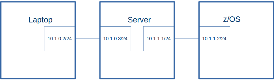
The laptop had
ip v4 address 10.1.0.2/24
routes
10.1.0.0/24 dev enp0s31f6 proto kernel scope link src 10.1.0.2 metric 100
10.1.0.0/24 via 10.1.0.2 dev enp0s31f6 proto static metric 100
10.1.1.0/24 via 10.1.0.3 dev enp0s31f6
ospf router id 1.2.3.4
The server had
ip v4 address 10.1.0.3/24
routes
10.1.0.0/24 dev eno1 proto kernel scope link src 10.1.0.3 metric 100
10.1.0.0/24 via 10.1.0.3 dev eno1 proto static metric 100
ospf router-id 9.2.3.4
The z/OS system has
ip v4 address 10.1.1.2
routes
10.1.0.0/24 via 10.1.1.1 on ETH1
10.1.1.0/24 dev tap0 proto kernel scope link src 10.1.1.1
Display the IP addresses in the network. Either use F OMP1,RTTABLE or for each router F OMP1,OSPF,LSA,LSTYPE=1,LSID=…. , LINK ID: is the IP address of the remote end, LINK DATA: is the IP address of the router’s end.
I configured multiple TCPIP subsystems, and each one had an OMPROUTE defined. I used a started task OEMP1, as the OMPROUTE for my base TCPIP.
If you have only one TCPIP subsystem, you can use OMPROUTE as your name.
F OMP1,OSPF,areasum
This displays the area summary.
AREA ID        AUTHENTICATION   #IFCS  #NETS  #RTRS  #BRDRS DEMAND
0.0.0.0           NONE              2      3      3      0  OFF
F OMP1,OSPF,EXTERNAL
EZZ7853I AREA LINK STATE DATABASE
TYPE LS DESTINATION     LS ORIGINATOR     SEQNO     AGE   XSUM
                # ADVERTISEMENTS:       0
                CHECKSUM TOTAL:         0X0
F OMP1,ospf,list,areas
“Displays all information concerning configured OSPF areas and their associated ranges.”
 EZZ7832I AREA CONFIGURATION 820
 AREA ID          AUTYPE          STUB? DEFAULT-COST IMPORT-SUMMARIES?
 0.0.0.0          0=NONE           NO          N/A           N/A

 --AREA RANGES--
 AREA ID          ADDRESS          MASK             ADVERTISE?
 0.0.0.0          11.11.0.0        255.255.255.0    YES
The entry with address 11.11.0.0 comes from the omproute configuration file entry
range ip_address=11.11.0.1
      subnet_mask=255.255.255.0
      ;
F OMP1,ospf,list,ifs
“For each OSPF interface, display the IP address and configured parameters as coded in the OMPROUTE configuation file”
 EZZ7833I INTERFACE CONFIGURATION 822
 IP ADDRESS      AREA             COST RTRNS TRDLY PRI HELLO  DEAD DB_EX
 10.1.3.2        0.0.0.0             1     5     1   1    10    40    40
 10.1.1.2        0.0.0.0             1     5     1   1    10    40    40
F OMP1,ospf,list,nbma
“Displays the interface address and polling interval related to interfaces connected to nonbroadcast multiaccess networks.”
F OMP1,OSPF,LSA,LSTYPE=2,LSID=10.1.0.3
EZZ7880I LSA DETAILS
LS OPTIONS:      E (0X02)
LS TYPE:         2
LS DESTINATION (ID): 10.1.0.3
LS ORIGINATOR:   9.2.3.4
NETWORK MASK:    255.255.255.0
 ATTACHED ROUTER: 1.2.3.4          (100)
 ATTACHED ROUTER: 9.2.3.4          (100)
Where (100) is the metric.
F OMP1,ospf,if
 EZZ7849I INTERFACES 832
 IFC ADDRESS     PHYS         ASSOC. AREA     TYPE   STATE  #NBRS  #ADJS
 10.1.3.2        JFPORTCP4    0.0.0.0         BRDCST   64      1      1
 10.1.1.2        ETH1         0.0.0.0         BRDCST   64      1      1
F OMP1,ospf,neighbor
EZZ7851I NEIGHBOR SUMMARY 834
 NEIGHBOR ADDR   NEIGHBOR ID     STATE  LSRXL DBSUM LSREQ HSUP IFC
 10.1.3.1        9.2.3.4           128      0     0     0  OFF JFPORTCP4
 10.1.1.1        9.2.3.4           128      0     0     0  OFF ETH1
F OMP1,ospf,routers
EZZ7855I OSPF ROUTERS 836
DTYPE RTYPE DESTINATION       AREA           COST       NEXT HOP(S)
  NONE
F OMP1,ospf,statistics
EZZ7856I OSPF STATISTICS 838
                 OSPF ROUTER ID:         10.1.1.2 (*OSPF)
                 EXTERNAL COMPARISON:    TYPE 2
                 AS BOUNDARY CAPABILITY: NO

 ATTACHED AREAS:                  1  OSPF PACKETS RCVD:             3336
 OSPF PACKETS RCVD W/ERRS:        0  TRANSIT NODES ALLOCATED:         84
 TRANSIT NODES FREED:            78  LS ADV. ALLOCATED:                1
 LS ADV. FREED:                   1  QUEUE HEADERS ALLOC:             32
 QUEUE HEADERS AVAIL:            32  MAXIMUM LSA SIZE:               512
 # DIJKSTRA RUNS:                 4  INCREMENTAL SUMM. UPDATES:        0
 INCREMENTAL VL UPDATES:          0  MULTICAST PKTS SENT:           3371
 UNICAST PKTS SENT:               7  LS ADV. AGED OUT:                 1
 LS ADV. FLUSHED:                 1  PTRS TO INVALID LS ADV:           0
 INCREMENTAL EXT. UPDATES:        0
F OMP1,OSPF,LSA,LSTYPE=2,LSID=10.1.0.3
Where
LSTYPE=2 is “Network links the set of routers attached to a network”.
10.1.0.3 is an LS destination (from F OMP1,ospf,database,areaid=…) It comes from the frr definition below
interface eno1
   ip address 10.1.0.3 peer 10.1.0.2/24
Only addresses on the Server are accepted. Addresses from the Laptop are not valid.
In the command F OMP1,OSPF,LSA,LSTYPE=1,LSID=1.2.3.4, some of the LINK IDs seem to be valid.
F OMP1,OSPF,LSA,LSTYPE=1,LSID=x.x.x.x
This allows you to see a lot of information about an individual element of the OSPF database.
The LSATYPE is described in here. LSTYPE=1 is for Router Links Advertisment.
The LSID is one of the routers, for example in
F OMP1,ospf,database,areaid=0.0.0.0, it displays, LS DESTINATION LS ORIGINATOR
F OMP1,ospf,neighbor, it displays NEIGHBOR ID
F OMP1,OSPF,LSA,LSTYPE=1,LSID=9.2.3.4
EZZ7880I LSA DETAILS
  LS DESTINATION (ID): 9.2.3.4
  LS ORIGINATOR:   9.2.3.4
  ROUTER TYPE:      (0X00)
  # ROUTER IFCS:   3
     LINK ID:          10.1.0.3
     LINK DATA:        10.1.0.3
        INTERFACE TYPE:   2
     LINK ID:          10.1.1.1
     LINK DATA:        10.1.1.1
        INTERFACE TYPE:   2
     LINK ID:          10.1.3.1
     LINK DATA:        10.1.3.1
        INTERFACE TYPE:   2
F OMP1,RTTABLE
EZZ7847I ROUTING TABLE 842
 TYPE   DEST NET         MASK      COST    AGE     NEXT HOP(S)

 STAT*  10.0.0.0         FF000000  0       16079   10.1.1.2
  SPF   10.1.0.0         FFFFFF00  101     16071   10.1.1.1         (2)
  SPF*  10.1.1.0         FFFFFF00  1       16078   ETH1
  SPF*  10.1.3.0         FFFFFF00  1       16078   JFPORTCP4
  SPF   11.1.0.2         FFFFFFFF  201     4733    10.1.1.1         (2)
                        0 NETS DELETED, 3 NETS INACTIVE
(2) is the number of equal-cost routes to the destination.
 OSPF Routing Process, Router ID: 1.2.3.4
 ...
 Number of areas attached to this router: 1
 Area ID: 0.0.0.0 (Backbone)
   Number of interfaces in this area: Total: 1, Active: 1
   Number of fully adjacent neighbors in this area: 1
   Area has no authentication
   SPF algorithm executed 4 times
   Number of LSA 5
   Number of router LSA 3. Checksum Sum 0x000109da
   Number of network LSA 2. Checksum Sum 0x000139df
   Number of summary LSA 0. Checksum Sum 0x00000000
   ...
There are 3 router Link States, and 2 network Link States; they are displayed below:
show ip ospf database
OSPF Router with ID (1.2.3.4)
  Router Link States (Area 0.0.0.0)
    Link ID         ADV Router      Age  Seq#       CkSum  Link count
    1.2.3.4        1.2.3.4          288 0x80000003 0x15a9 1
    9.2.3.4        9.2.3.4          288 0x80000007 0x56f1 2
    10.1.1.2       10.1.1.2        1078 0x8000001e 0x9d40 1
  Net Link States (Area 0.0.0.0)
    Link ID         ADV Router      Age  Seq#       CkSum
    10.1.0.3       9.2.3.4          289 0x80000001 0x7ba2
    10.1.1.2       10.1.1.2        1082 0x80000003 0xbe3d
show ip ospf database router self-originate
This shows the links attached to this OSPF environment.
OSPF Router with ID (9.2.3.4)
Router Link States (Area 0.0.0.0)
Link State ID: 9.2.3.4
Number of Links: 2
  Link connected to: Stub Network
  (Link ID) Net: 10.1.0.0
  (Link Data) Network Mask: 255.255.255.0

  Link connected to: a Transit Network
  (Link ID) Designated Router address: 10.1.1.2
  (Link Data) Router Interface address: 10.1.1.1
show ip ospf database router
  OSPF Router with ID (1.2.3.4)
  Router Link States (Area 0.0.0.0)
===================================
  LS age: 387
  Options: 0x2  : *|-|-|-|-|-|E|-
  LS Flags: 0x3
  Flags: 0x0
  LS Type: router-LSA
  Link State ID: 1.2.3.4
  Advertising Router: 1.2.3.4
  ...
  Length: 36

  Number of Links: 1

  Link connected to: a Transit Network
    (Link ID) Designated Router address: 10.1.0.3
    (Link Data) Router Interface address: 10.1.0.2
   ...
===================================
  LS Type: router-LSA
  Link State ID: 9.2.3.4
  Advertising Router: 9.2.3.4

 Number of Links: 2
 Link connected to: a Transit Network
  (Link ID) Designated Router address: 10.1.0.3
  (Link Data) Router Interface address: 10.1.0.3

 Link connected to: a Transit Network
  (Link ID) Designated Router address: 10.1.1.2
  (Link Data) Router Interface address: 10.1.1.1
===================================
  LS Type: router-LSA
  Link State ID: 10.1.1.2
  Advertising Router: 10.1.1.2
  Number of Links: 1
  Link connected to: a Transit Network
   (Link ID) Designated Router address: 10.1.1.2
   (Link Data) Router Interface address: 10.1.1.2
show ip ospf database router 9.2.3.4
laptop# show ip ospf database router 9.2.3.4
OSPF Router with ID (1.2.3.4)
Router Link States (Area 0.0.0.0)
LS Type: router-LSA
Link State ID: 9.2.3.4
Advertising Router: 9.2.3.4
Number of Links: 2
  Link connected to: a Transit Network
  (Link ID) Designated Router address: 10.1.0.3
  (Link Data) Router Interface address: 10.1.0.3

  Link connected to: a Transit Network
  (Link ID) Designated Router address: 10.1.1.1
  (Link Data) Router Interface address: 10.1.1.1
show ip ospf database network
laptop# show ip ospf database network

  OSPF Router with ID (1.2.3.4)
  Net Link States (Area 0.0.0.0)
  ====
  LS age:
  LS Type: network-LSA
  Link State ID: 10.1.0.3 (address of Designated Router)
  Advertising Router: 9.2.3.4

  Network Mask: /24
    Attached Router: 1.2.3.4
    Attached Router: 9.2.3.4
  ====
  LS age:...
  LS Type: network-LSA
  Link State ID: 10.1.1.2 (address of Designated Router)
  Advertising Router: 10.1.1.2
  Network Mask: /24
    Attached Router: 10.1.1.2
    Attached Router: 9.2.3.4
show ip ospf route
Server# show ip ospf route
============ OSPF network routing table ============
N    10.1.0.0/24           [100] area: 0.0.0.0
                           directly attached to eno1
N    10.1.1.0/24           [10000] area: 0.0.0.0
                           directly attached to tap0
N    10.1.3.0/24           [10000] area: 0.0.0.0
                           directly attached to tap2
N    11.1.0.2/32           [200] area: 0.0.0.0
                           via 10.1.0.2, eno1
Where
N is the route type,
N, Network, Intra area
N IA, network, Inter area
D IA, Discard Inter area
10.1.0.0.24 is the IP address
[] is the cost
0.0.0.0 is the area
show ip ospf interface enp0s31f6
This command shows the interface on the local system. I’ve displayed what I think is important. There are many more parameters, and it is missing the description from the configuration file!
enp0s31f6 is up
  ...
  ifindex 2, MTU 1500 bytes, BW 1000 Mbit <UP,BROADCAST,RUNNING,MULTICAST>
  Internet Address 10.1.0.2/24, Broadcast 10.1.0.255, Area 0.0.0.0
  Router ID 1.2.3.4, Network Type BROADCAST, Cost: 100
  Designated Router (ID) 9.2.3.4 Interface Address 10.1.0.3/24
  Backup Designated Router (ID) 1.2.3.4, Interface Address 10.1.0.2
  Neighbor Count is 1, Adjacent neighbor count is 1
  ...
This just shows a setting – or Router Information is disabled on this router.
show ip route
The output below shows there is one OSPF defined route (which has been active for 1 hour 9:51 minutes). (There are other routes defined.)
Codes: K - kernel route, C - connected, S - static, R - RIP,
       O - OSPF, I - IS-IS, B - BGP, E - EIGRP, N - NHRP,
       T - Table, v - VNC, V - VNC-Direct, A - Babel, F - PBR,
       f - OpenFabric,
       > - selected route, * - FIB route, q - queued, r - rejected, b - backup
       t - trapped, o - offload failure

K>* 0.0.0.0/0 [0/600] via 192.168.1.254, wlp4s0, 01:10:41
O   10.1.0.0/24 [110/100] is directly connected, enp0s31f6, weight 1, 01:10:41
K * 10.1.0.0/24 [0/100] via 10.1.0.2, enp0s31f6, 01:10:41
C>* 10.1.0.0/24 is directly connected, enp0s31f6, 01:10:41
O   10.1.1.0/24 [110/10100] via 10.1.0.3, enp0s31f6, weight 1, 01:09:51
K>* 10.1.1.0/24 [0/0] via 10.1.0.3, enp0s31f6, 01:10:41
K>* 10.2.1.0/24 [0/0] is directly connected, enp0s31f6, 01:10:41
K>* 10.3.1.0/24 [0/0] via 10.1.0.3, enp0s31f6, 01:10:41
K>* 169.254.0.0/16 [0/1000] is directly connected, virbr0 linkdown, 01:10:41
C>* 192.168.1.0/24 is directly connected, wlp4s0, 01:10:41
show ip rpf
Codes: K - kernel route, C - connected, S - static, R - RIP,
       O - OSPF, I - IS-IS, B - BGP, E - EIGRP, N - NHRP,
       T - Table, v - VNC, V - VNC-Direct, A - Babel, F - PBR,
       f - OpenFabric,
       > - selected route, * - FIB route, q - queued, r - rejected, b - backup
       t - trapped, o - offload failure

C>  10.1.0.0/24 is directly connected, enp0s31f6, 01:12:22
C>  192.168.1.0/24 is directly connected, wlp4s0, 01:12:22
O – router’s willingness to receive and forward Opaque-LSAs
DC – Handling of Demand Circuits
EA” : “-“, describes the router’s willingness to receive and forward External Attributes LSAs
N/P – if area is NSSA.
MC – Multicast datagrams forwarded
E – external link advertisements are not flooded into OSPF
M/T – Multi-Topology (MT) Routing in OSPF
T – router’s TOS capability
and flags are:
SELF 0x01
SELF_CHECKED 0x02
RECEIVED 0x04
APPROVED 0x08
DISCARD 0x10
LOCAL_XLT 0x20
PREMATURE_AGE 0x40
IN_MAXAGE 0x80
Other information
ip -4 route
colinpaice@colinpaice:~$ ip -4 route
default via 192.168.1.254 dev wlp4s0 proto dhcp metric 600
10.1.0.0/24 dev enp0s31f6 proto kernel scope link src 10.1.0.2 metric 100
10.1.0.0/24 via 10.1.0.2 dev enp0s31f6 proto static metric 100
10.1.1.0/24 via 10.1.0.3 dev enp0s31f6
10.2.1.0/24 dev enp0s31f6 scope link
10.3.1.0/24 via 10.1.0.3 dev enp0s31f6
169.254.0.0/16 dev virbr0 scope link metric 1000 linkdown
192.168.1.0/24 dev wlp4s0 proto kernel scope link src 192.168.1.222 metric 600
192.168.122.0/24 dev virbr0 proto kernel scope link src 192.168.122.1 linkdown
I found that understanding the flows between to OSPF nodes helped me understand OSPF.
I used Wireshark to trace the data sent from my OSPF router with id 9.2.3.4.
There are four basic flows
My router sending configuration information to the remote router
The remote router sending acknowledgments back to my router
The remote router sending configuration information to my router (the same as 1. above, but in the opposite direction)
My router sending acknowledgements back to the remote router (the same as 2., but in the opposite direction).
It looks like a lot of data flowing – but I focused on my router sending information to the remote router.
Background information
Link state information helps others build a map of the configuration. This gives status information about the links.
Each router sends “new” information to the remote end of the connection; for example a Link State Update. The remote end acknowledges these with a Link State Acknowledgement.
While the local router is sending stuff to the remote router, the remote router is sending it’s configuration information to the local router.
Once the configuration information has been exchanged, and the configuration information stabilises, there is still a periodic “Hello Packet” between each router. This is a heartbeat to tell the remote end that the local end is still alive. The “Hello Packet” is sent out typically every 10 seconds. Updates are sent out around the “Hello Packet” time, so changes typically propagate through the network, 10 seconds a hop.
Information is exchanged via Link State Advertisement (LSA) which advertises the state of a link.
LSA type 1 is for routers, it contains information about routers
LSA type 2 is for networks, it contains information about IP addresses
Stub areas.
If you had all boxes in one big area – every box will know about other boxes. This may not scale well.
You can create areas, for example an area could be a country. Areas are connected together through the backbone area, area 0. An area, such as area1, can have information such as for addresses in area 17, go via the default routing to the backbone, and let the router where area 1 joins the backbone area sort out the routing.
Nodes in area 1need fewer definitions – as the definitions just say “go by the backbone”
Summary
I restarted my laptop, and it joined the network. It’s configuration was
OSPF router id 1.2.3.4
Somewhere else in the network a node received two flows
Flow 1
I am router, 9.2.3.4
Type 1 Router-LSA. I have 3 direct connections
Remote end’s IP address 10.1.1.2, my address 10.1.1.1
Remote end’s IP address 10.1.3.2, my address 10.1.3.1
Remove end’s IP address 10.1.0.3, my address 10.1.0.3
Type 2- Network LSA
Attached routers 1.2.3.4 and 9.2.3.4
Flow 2
I am router 1.2.3.4
Type 1 Router LSA
I have IP address 10.1.0.0 type stub
I have IP address 12.1.0.1 type stub.
If the configuration changes, such as a new address is added to the node, the data broadcast is the current configuration.
Each system supporting OSPF gets the same information and can build up a database of the network, and can make informed routing decisions.
Changing the configuration
Adding an address to a link
I used the command
sudo ip -4 addr add 12.12.0.1 dev enp0s31f6
to add an additional IP address to the Ethernet connection on my laptop. The command
ip -4 addr gave
enp0s31f6: <BROADCAST,MULTICAST,UP,LOWER_UP> mtu 1500 qdisc fq_codel state UP group default qlen 1000
    inet 10.1.0.2/24 brd 10.1.0.255 scope global noprefixroute enp0s31f6
       valid_lft forever preferred_lft forever
    inet 12.13.0.1/32 scope global enp0s31f6
       valid_lft forever preferred_lft forever
    inet 12.14.0.1/32 scope global enp0s31f6
       valid_lft forever preferred_lft forever
    inet 12.12.0.1/32 scope global enp0s31f6
       valid_lft forever preferred_lft foreverd
This cause a flow to the z/OS system, saying “this is all the IP addresses I know about”.
LS Update Packet
 Number of LSAs: 1
 LSA-type 1 (Router-LSA), len 72
  LS Type: Router-LSA (1)
  Link State ID: 1.2.3.4
  Advertising Router: 1.2.3.4
   Number of Links: 4
    Type: Transit  ID: 10.1.0.3        Data: 10.1.0.2        Metric: 100
     Type: Stub     ID: 12.13.0.1      Data: 255.255.255.255 Metric: 100
     Type: Stub     ID: 12.14.0.1      Data: 255.255.255.255 Metric: 100
     Type: Stub     ID: 12.12.0.1      Data: 255.255.255.255 Metric: 100
The transit address was the original address.
The stub address(es) were added manually.
Deleting an address to a link
I used the command
sudo ip -4 addr del 12.12.0.1 dev enp0s31f6
to remove the link I had previously added.
This cause a flow to the z/OS system, saying “this is all the IP addresses I know about” – omitting the address I had just deleted.
LS Update Packet
 Number of LSAs: 1
 LSA-type 1 (Router-LSA), len 72
  LS Type: Router-LSA (1)
  Link State ID: 1.2.3.4
  Advertising Router: 1.2.3.4
   Number of Links: 4
     Type: Transit ID: 10.1.0.3  Data: 10.1.0.2        Metric: 100
     Type: Stub    ID: 12.13.0.1 Data: 255.255.255.255 Metric: 100
     Type: Stub    ID: 12.14.0.1 Data: 255.255.255.255 Metric: 100
     Type: Stub    ID: 12.12.0.1 Data: 255.255.255.255 Metric: 100
One way flows in more detail
The “Hello packet”
I have Source OSPF router 9.2.3.4, area 0.0.0.0
DB Description
Source OSPF router 9.2.3.4, area 0.0.0.0
DB Description
“I know about…”
Source ospf router 9.2.3.4, area 0.0.0.0
LSA-type 1 (Router-LSA) Link State ID 1.2.3.4 advertising 1.2.3.4
LSA-type 1 (Router-LSA) Link State ID 9.2.3.4 advertising 9.2.3.4
LSA-type 1 (Router-LSA) Link State ID 10.1.1.2 advertising 10.1.1.2
LSA-type 2 (Network-LSA) Link State ID 10.1.0.2 advertising 1.2.3.4
LSA-type 2 (Networ-kLSA) Link State ID 10.1.1.2 advertising 10.1.1.2
Link state update
“Here is information about the links and the IP addresses”.
Source router 9.2.3.4, Area 0.0.0.0
LSA-type 1 (Router-LSA) Link State ID 1.2.3.4 advertising 1.2.3.4
Links: Type Transit ID 10.1.0.2 Data 10.1.0.2 Metric 100
LSA-type 1 (Router-LSA) Link State ID 9.2.3.4 advertising 9.2.3.4
Links: Type Transit ID 10.1.0.2 Data 10.1.0.3 Metric 100
Links: Type Stub ID 10.1.1.0 Data 255.255.255.0 Metric 1000
LSA-type 1 (Router-LSA) Link State ID 10.1.1.2 advertising 10.1.1.2
Links: Type Transit ID 10.1.1.1 Data 10.1.1.2 Metric 1
LSA-type 2 (Network-LSA) Link State ID 10.1.0.2 advertising 1.2.3.4
Attached router: 1.2.3.4
Attached router 9.2.3.4
LSA-type 2 (Network-LSA) Link State ID 10.1.1.2 Advertising 10.1.1.2
Attached router 10.1.1.2
Attached router 9.2.3.4
DB Description
I have OSPF router 9.2.3.4, Area 0.0.0.0
I support external routing
Link state update (2)
Source router 9.2.3.4, Area 0.0.0.0
Link State Type Router
LSA-type 1 (Router-LSA) Link State ID 9.2.3.4 advertising 9.2.3.4
Links: Type Transit ID 10.1.0.2 Data 10.1.0.3 Metric 100
Links: Type Transit ID 10.1.1.1 Data 10.1.1.1 Metric 1000
LSA-type 1 (Router-LSA) Link State ID 10.1.1.1 advertising 9.2.3.4
Attached router: 9.2.3.4
Attached router: 10.1.1.2
Hello Packet
Periodically (every 10 or so seconds) there is a Hello Packet flow, which acts as a heartbeat to let the remote end the know the local end is still alive.
This is another blog post in the series “One minute…” which gives the basic concepts of a topic, with enough information so that you can read other documentation, but without going too deeply.
IP networks can range in size from 2 nodes(machines), to millions of nodes(machines), and a packet can go from my machine to any available machines – and it arrives! How does this miracle work?
I’ll work with IP V6 to make it more interesting (and there is already a lot of documentation for IP V4)
I have and old laptop, connected by Ethernet to my new laptop. My new laptop is connected by wireless to my server which is connected to z/OS. I can ping from the old laptop to z/OS.
Each machine needs connectivity for example wireless, Ethernet, or both.
Each machine has one or more interfaces where the connectivity comes in (think Ethernet port, and Wireless connection). This is sometimes known as a device.
Each interface has one or more IP addresses.
You can have hardware routers, or can route through software, without a hardware router. A hardware router can do more than route.
Each machine can route traffic over an interface (or throw away the packet).
If there is only one interface this is easy – all traffic goes down it.
If there is more than one interface you can specify which address ranges go to which interface.
You can have a default catch-all if none of the definitions match
You can have the same address using different interfaces, and the system can exploit metrics to decide which will be used.
You can have policy based routing. For example
packets from this premier user, going to a specific IP address should use the high performance (and more expensive) interface,
people using the free service, use the slower(and cheaper) interface.
Modern routing uses the network topology to manage the routing tables and metrics in each machine.
Static
The administrator defines a table of “if you want get to… then use this interface, the default is to send the packet using this … interface”. For example with z/OS
BEGINRoutes
;     Destination   SubnetMask    FirstHop    LinkName  Size
; ROUTE 192.168.0.0 255.255.255.0       =     ETH2 MTU 1492
ROUTE 10.0.0.0      255.0.0.0           =     ETH1 MTU 1492
ROUTE DEFAULT                     10.1.1.1    ETH1 MTU 1492
ROUTE 10.1.0.0      255.255.255.0   10.1.1.1  ETH1 MTU 1492

ROUTE 2001:db8::/64 fe80::f8b5:3466:aa53:2f56 JFPORTCP2 MTU 5000
ROUTE fe80::17      HOST =                    IFPORTCP6 MTU 5000
ROUTE default6      fe80::f8b5:e4ff:fe59:2e51 IFPORTCP6 MTU 5000

ENDRoutes
Says
All traffic for 10.*.*.* goes via interface ETH1.
If no rule matches (for IP V4) use the DEFAULT route via ETH1. The remote end of the connection has IP address 10.1.1.1
All traffic for IPV6 address 2001:db8:0:* goes via interface JFPORTCP2
If no rule matches (for IP V6) use the DEFAULT6 route via IFPORTCP6. The remote end of the connection has IP address fe80::f8b5:e4ff:fe59:2e51.
On Linux the ip route command gave
default via 192.168.1.254 dev wlxd037450ab7ac proto dhcp metric 600
10.1.0.0/24 dev eno1 proto kernel scope link src 10.1.0.3 metric 100
10.1.1.0/24 dev tap0 proto kernel scope link src 10.1.1.1
This says
The default is to send any traffic via device wlxd037450ab7ac.
Any traffic for 10.1.0.* goes via device eno1
Any traffic for 10.1.1.* goes via device tap0.
Routing Information Protocol(RIP)
Manually assigning metrics (priorities) to hint which routes are best, quickly becomes unmanageable when the number of nodes(hosts) increases.
If the 1980’s the first attempt to solve this was using RIP. It uses “hop count” of the destination from the machine as a metric. A route with a small hop count will get selected over a route with a large hop count. Of course this means that each machine needs to know the topology. RIP can support at most 15 hops.
Each node participating in RIP learns about all other nodes participating in RIP.
Every 30 seconds each node sends to adjacent nodes “I know about the following nodes and their route statements”. Given this, eventually all nodes connected to the network will know the complete topology. For example, from the frr(Free Range Routing) trace on Linux
RIPng update timer expired!
RIPng update routes on interface tap1
  send interface tap1
  SEND response version 1 packet size 144
   2001:db8::/64 metric 1 tag 0
    2001:db8:1::/64 metric 1 tag 0
   2002::/64 metric 2 tag 0
    2002:2::/64 metric 2 tag 0
   2008::/64 metric 3 tag 0
    2009::/64 metric 1 tag 0
    2a00:23c5:978f:6e01::/64 metric 1 tag 0
This says
The 30 second timer woke up
It sent information to interface tap1
2001:db8::/64 metric 1 this is on my host(1 hop)
2002::/64 metric 2 this is from a router directly connected to me (2 hops).
2008::/64 metric 3 is connected to a router connected to a router directly connected to me (3 hops.)
To get to 2002::/64 go down interface with the IP address FE80::E42D:73FF:FEB1:1AB8.
This route has been provided by the RIP code.
The destination is 3 hops away (in the information sent from the server it was 2 hops away)
The fields are
RIP – Indicates a route that was learned through the IPv6 RIP protocol.
* An asterisk (*) after the route type indicates that the route has a directly connected backup.
Cost 3 – this route is 3 hops away.
Age 10 -Indicates the time that has elapsed since the routing table entry was last refreshed
OSPF (Open Shortest Path First)
OSPF was developed after RIP, as RIP had limitations – the maximum number of hops was 15, and every 30 seconds there was a deluge of information being sent around. The OSPF standard came out in 1998 10 years after RIP.
The 10 second picture
You create areas in your network. An area could be a building, or a city. The backbone or area 0 is connected to your area.
Within an area all computers have a map of IP addresses in the area, and how to get to them. If you define a new address for a link on one computer or add a new router , all of the computers in the area get updated within seconds.
The more detailed picture
Using OSPF, when a system starts up it sends to the neighbouring systems “Hello, my router id is 9.3.4.66, and I have the following IP addresses and routes.” This information is propagated to all nodes in the OSPF area. When a node receives this information it updates its internal map (database) with this information. Every 10 seconds or so, each node sends a “Hello Packet” to the adjacent nodes to say “I’m still here”. If this packet is not received, then the (working) node can broadcast “The node …. is not_responsive/dead”, and all other nodes can then update their maps.
If the configuration changes, for example an IP address is added to an interface, the node’s information is propagated to a ‘managing node’ and its backup, and this propagates the update throughout the network. In a stable network, the network traffic is just the “Hello packet” sent to the next node, and any configuration changes propagated.
One of the pieces of information sent out about node’s route is the metric or “cost”. When a node is deciding which interface to route a packet to, OSPF can calculate the overall “cost” and if there are a choice of routes to the destination it can decide which interface gives the best cost.
To make it easier to administer, you can have areas, so you might have an area being the UK, another area being Denmark, and another area being the USA.
How it works on Linux
OSPF plugs its map of the network into the IP router code. When the IP router gets a packet it looks at its internal tables, including the OSPF data to decide on the best route.
This is another of those little tasks that look simple but turn out to be more a little more complex than it first looked.
Authentication in OSPF is performed by sending authentication data in every flow. This can be a password (not very secure) or an MD5 check sum, based on a shared password and sequence number. The receiver checks the data sent is valid, and matches the data it has.
To do any authentication you need to enable it at the area level.
router ospf
  ospf router-id 9.2.3.4
  area 0.0.0.0 authentication
This turns it on for all interfaces – defaulting to password based with a null password. I did this and my connections failed because the two ends of the link were configured differently.
I first had to configure ip ospf authentication null for all interfaces, then enable area authenticate, and the the connections to other systems worked.
interface tap2
   ip ospf area 0.0.0.0
   ip ospf authentication null

interface ...

router ospf
  ospf router-id 9.2.3.4
  area 0.0.0.0 authentication
I could then enable the authentication on an interface by interface basis.
If there is a mismatch,
z/OS will report a mismatch,
frr quietly drops the packet. I enabled packet trace.
The router ospf … area … authentication is the master switch.
To define authentication on a link, you have to change both ends, then activate the change at the same time at each end.
On z/OS
I could not find how to get OMPROUTE to reread its configuration file after I updated and OSPF entry. There is an option
f OMP1,reconfig
but the documentation says
RECONFIG Reread the OMPROUTE configuration file. This command ignores all statements in the configuration file except new OSPF_Interface, RIP_Interface, Interface, IPv6_RIP_Interface, and IPv6_Interface statements.
and I got messages like
EZZ7821I Ignoring duplicate OSPF_Interface statement for 10.1.1.2
For z/OS OMPROUTE to communicate with frr (and CISCO routers) I had to specify the z/OS definition Authentication_… for example
If you use a password, then it flows in clear text. Anyone sniffing your network will see it. It should not be used to protect your system.
On frr
You need router ospf area … authentication. If you have area … authentication message-digest then the password authentication statement on the interface is ignored.
router ospf
  ospf router-id 9.2.3.4
  router-info area
  area 0.0.0.0 authentication

interface tap0
   ip ospf authentication colin
   ...
key id – an integer in the range 0-255. In the future this key could be used to specify which checksum algorithm to use. Currently only its value is used only as part of the check sum calculation.
the increasing sequence number of the flow.
This checksum is calculated and the sequence number and checksum are sent as part of each flow. The remote end performs the same calculation, with the same data, and the checksum value should match.
Because the sequence number changes with every flow, the checksum value changes with every flow. This prevents replay attacks.
The key must be the same on both ends of the connection. Because frr and hardware routers are based in ASCII, an ASCII value must be specified when using z/OS and these routers.
On frr
router ospf
  ospf router-id 9.2.3.4
  area 0.0.0.0 authentication

interface tap0
   ip ospf authentication message-digest
   ip ospf message-digest-key 3 md5 AAAAAAAAAAAAAAAA
Authentication_Key The value of the authentication key for this interface. This value must be the same for all routers attached to a common medium a link. The coding of this parameter depends on the authentication type being used on this interface. …
For authentication type MD5, code the 16-byte authentication key used in the md5 processing for OSPF routers attached to this interface.
This value must be the same at each end.
If the router at the remote end is ASCII based, for example CISCO or Extreme routers, or the frr package on Linux, this value must be specified in ASCII.
You can specify a value in ASCII as A”ABCD…” or as hexadecimal 0x41424344…”, were 41424344 is the ASCII for ABCD.
For non ASCII routers you can specify an ASCII or hexadecimal value. You can use pwtokey to generate a suitable hexadecimal key from a password.
This morning my Ethernet connection between my two Linux systems stopped working. I could see IPV6 stuff flowing over the network, but Linux did not say connected. Also there was no IPV4 address. It took me almost a day to work out what the problem was. Googling and following the advice may have made it worse!
I also include some useful commands for next time it happens.
Using Wireshark I could see IPV6 traffic flowing over the connection, so the cable was OK, and some of the definitions were OK.
The ip addr command showed there was an IPV6 address for the connection, but no IPV4 address.
I could not find a log for Network Manager with its error messages, see log below for the messages on syslog.
Looking online, there were suggestions that you delete your existing definition and recreate it, also use nm-connection-editor. This may have been a bad move; it is always better to rename than to delete.
Comparing the definitions currently in use /etc/NetworkManager/system-connections/ with a backup version, I could see that the .nmconnection files were in use.
I used Network Manager to change my Ethernet definitions. Under the IPv4 tab
IPv4 method: change from Automatic(DHCP) to Manual
I was looking into configuring IP V6 on my z/OS running on zPDT running on Linux. I could not understand why configuring the IP V6 link between Linux and z/OS was so difficult.
IP V6 address for use within a connection are like fe80::b0b6:daff:fe64:77f5 where b0b6:daff:fe64:77f5 is based on the MAC(hwaddr). On many systems, this value does not change across IPLs – and so most of the documentation uses the “constant” value.
The connection between Linux and z/OS is a “tap” interface (a kernel virtual device) which looks like an OSA adapter to z/OS.
I found a comment
Each TAP device has a random MAC address that is used as source address.
This explains why the connection was getting a different IP address every time I ipled.
On z/OS you defined a route using this IP address, for example
BEGINRoutes
ROUTE 2001:db8::7/128 fe80::3f:67ff:fe08:51dc   IFPORTCP6   MTU 5000
ENDRoutes
To get round this problem you need to explicitly define an address on Linux
sudo ip -6 addr add fec0::cccc/64 dev tap1
where cccc is for my initials!
You then put this address into the z/OS routing statements.
BEGINRoutes
ROUTE 2001:db8::7/128 fe80::cccc   IFPORTCP6   MTU 5000
ENDRoutes
As part of understanding how IP V6 dynamic routing works, I managed to get my little home network to talk using IP V6.
Privacy
There are sites which can give you your geographic location from your IP V6 address. One site gave me the top part of my post code, the latitude and longitude of my garage, and my ISP provider. So instead of giving real IP addresses, Ive used xxxx:xxxx:xxxx:xxxx for the IP V6 address provided by my Internet Service Provider, and using the 2001:db8::/64 address which is assigned for documentation use.
My network for the easy bit
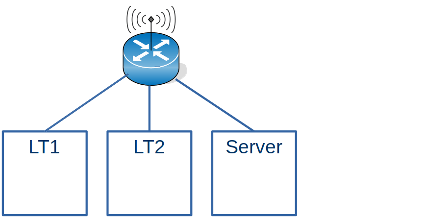
I have 2 Laptops and a Server all running Linux.
From my internet router I could see the information for LT2
Where GUA is the Global address (known outside of my network).
On Linux I can use the ip -6 addr command to display the address of the connection. A connector can have more than one address.
On the server machine, the addresses were
wlxd037450ab7ac: <BROADCAST,MULTICAST,UP,LOWER_UP> mtu 1500 state UP qlen 1000
  inet6 xxxx:xxxx:xxxx:xxxx:7694:3711:8f98:7271/64 scope global temporary dynamic...
  inet6 xxxx:xxxx:xxxx:xxxx:a5e4:61a:b3b2:9d8b/64 scope global dynamic mngtmpaddr noprefixroute ...
  inet6 fe80::216a:2b1d:c908:eb39/64 scope link noprefixroute
Every time I rebooted, the xxxx… was the same, but the rest of the address was different.
The global address share the same prefix xxxx:xxxx:xxxx:xxxx/64, which is the address my Internet Service Provider allocated to my home.
The Link-Local fe80:: is only used within the use of its interface. The address should be stable across reboots, but may change if you change the configuration.
Talking between the Linux systems.
On LT2 I could issue ping xxxx:xxxx:xxxx:xxxx:7694:3711:8f98:7271 to the Server, and this worked.
Create your own addresses
The string xxxx:xxxx:xxxx:xxxx:7694:3711:8f98:7271 is very long, and changes every time I restart Linux. This means I had to manually type the long address in when trying to use it This was tedious for ping, and if I used ssh to logon to the box, every time it asked me about the authentication of the host.
You can create your own address for an interface.
sudo ip -6 addr add xxxx:xxxx:xxxx:xxxx::cccc dev wlxd037450ab7ac
It has to use the same 64 left bits xxxx:xxxx:xxxx:xxxx,;the remaining bits can be almost anything. I like nice short ::4 or ::cccc type values
I issued that command on the server, and I was able to successfully ping that address from my laptop. How does that work?
On my laptop I issued the ping command. Linux did not have any routing information for it, so it was sent using the default route to the wireless router.
The wireless router did not know about the address, so issued a multicast address to all(3) systems connected to it. “Does any one have xxxx:xxxx:xxxx:xxxx::cccc”.
Laptop1 got the request – and as it did not have the address – it ignored the request.
The Server got the request – and as it did have the address – it replied “I have xxxx:xxxx:xxxx:xxxx::cccc”.
The wireless router then forwards the ping request to the server, and cached the routing information.
If you look at the response times of the ping you can see the first request takes a long time
colinpaice@colinpaice:~$ ping  xxxx:xxxx:xxxx:xxxx::cccc
PING xxxx:xxxx:xxxx:xxxx::cccc(xxxx:xxxx:xxxx:xxxx::cccc) 56 data bytes
64 bytes from xxxx:xxxx:xxxx:xxxx::cccc: icmp_seq=1 ttl=64 time=383 ms
64 bytes from xxxx:xxxx:xxxx:xxxx::cccc: icmp_seq=2 ttl=64 time=74.5 ms
64 bytes from xxxx:xxxx:xxxx:xxxx::cccc: icmp_seq=3 ttl=64 time=6.95 ms
This information is cached on the Linux, and in the router.
For example ip -6 neigh gives
xxxx:xxxx:xxxx:xxxx::88 dev wlp4s0 lladdr 00:24:d6:5e:2e:d2 REACHABLE
After a few minutes the output is
xxxx:xxxx:xxxx:xxxx::88 dev wlp4s0 lladdr 00:24:d6:5e:2e:d2 STALE
The time for an entry to become stale is based on /proc/sys/net/ipv6/neigh/…/base_reachable_time. On my Linux system this is 30 seconds.
The above was the easy bit….
A more complex example – adding in a host without wireless access.
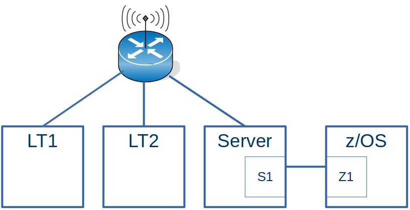
Laptop to z/OS
This configuration is the same as the first example with the addition of an Ethernet connection going to z/OS.
For z/OS to work with the Laptops, the wireless router needs to be told about the IP addresses on z/OS
One of the addresses for z/OS on the Ethernet-like connection from the server is 2001:db8:e::9. There are no 2a00… (xxxx…) addresses on z/OS because z/OS is not attached to the wireless network.
If I ping the 2001:db8:e::9 address from a laptop, it does not complete successfully. Looking at the traffic from the wireless router to the server, there is no traffic for 2001:db8:…
I had to use radvd on the Server to act as a router. The radvd configuration for the wireless router was
The route…{} says I (the Linux system) know about this IP address range.
When this was activated, I could see a router advertisement of 2001:db8:e::/64 being sent to the wireless router. After this, there was traffic from the wireless router down to the server.
Ping to 2001:db8:1::9 on z/OS was successful. I stopped the radvd process on the server, and after about 3 minutes ping stopped working. This is because the information sent from radvd into wireless router gets stale and eventually deleted. Typically the radvd tasks sends the information regularly, so the wireless router has up to date routing information.
The source of the ping was xxxx:xxxx:xxxx:xxxx:84ce:f350:1dce:b4bf, the Laptop end of the wireless connection.
On z/OS this was routed through via the default route, xxxx:xxxx:xxxx:xxxx:84ce:f350:1dce:b4bf which was the Server end of the connection from z/OS.
The server either knew the route to my laptop, or it used the default to send it view the wireless router, which knew to send it to the laptop.
Pinging from z/OS
From z/OS I could successfully ping xxxx:xxxx:xxxx:xxxx:84ce:f350:1dce:b4bf. The request went via the z/OS default route to the server, and then via the wireless router to the laptop.
The reply (destination 2001:db8:1::9) went via the route described in laptop to z/OS above.
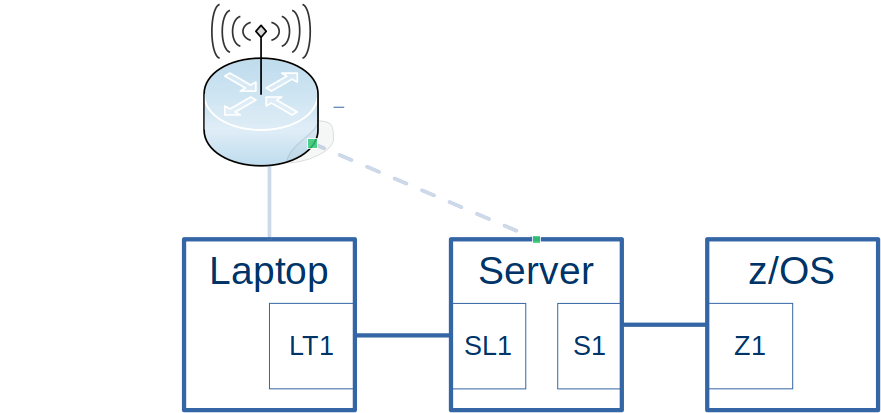
An even more complex example – doing it without using defaults.
I had this situation because the wireless dongle on the server was not very reliable and kept dropping the connection. This made it very hard to diagnose problem, as sometimes a ping would work – and a short while later, it would not work – and I assumed it was the configuration changes I was making.
Now that I understand more about Dynamic Routing and Neighbor Discovery, setting this up was remarkably easy. I’m sure there must be something I have missed.
Usually when I used ping on my laptop, it used the IP address I had created, 2008::5. I could see this in the Wireshark trace going to z/OS. When playing around with the wireless adapter, sometimes ping used the wireless address, and the ping failed, because z/OS did not know how to route back to the wireless address. Ping gave me a warning Warning: source address might be selected on device other than: enp0s31f6.
sudo ip -6 route add 2001:0db8:1::9/64 dev tap1
sudo ip -6 route del 2001:0db8:1::9/64 dev tap1
sudo ip -6 route flush 2001:0db8:1::9/64 dev tap1
sudo ip -6 -statistics route flush 2001:0db8:1::9/64 dev tap1
Some information may be stored in the neighbour cache so you may need to use commands like:
sudo ip -6 neigh flush to 2001:db8:1::9
sudo ip -6 neigh flush dev tap1
z/OS
You define static routes between BEGINRoutes and ENDRoutes. If you want to change one entry, you have to replace all entries. You cannot add or remove individual entries.
You cannot have an empty BEGINRoute… ENDRoute. If used, it has to have at least one entry. You can create a dummy entry that will never be used.
You can change this file, and use the OBEY command to activate it
v tcpip,tcpip,obeyfile,USER.Z24C.TCPPARMS(routefc)
To delete an entry, remove it from the file, and activate the file.
Dynamic routes
Dynamic routes are created from facilities like radvd on Linux. This defines capability available on an interface.

 ColinPaice